///BMW M Power
Where to start depends on where you wish to finish, turbocharging your M10 engine should not be considered until much thought and planning has been completed. Things that need to be addressed include:
What will the intended use be?
Street
Autocross
Roadcourse/Street
Full racing
Drag Racing
What are the realistic goals for power production?
What fuel grade is available?
How much money do you want to spend?
How will the rest of the vehicle be modified to handle the power goal?
Cooling, clutch, etc
Realistic power production goals for premium pump fuel available in North America (some better than others) for the M10 engine are between 150-175hp/L now keep in mind that this is not for a simple bolt on system. Bolt-on systems which maintain the stock engine control systems will be limited to fuel delivery as well as the limitations within the stock engine.
If you are building a race only engine then the rules of the class as well as the rules for fuel are the only limiters (as well as budget). In its ultimate form BMW build a production M10 block M12/13 S10B15 1.5L turbocharged 16V engine for Formula 1 that produced in excess of 1280hp(as high as the dyno would display) Some estimated that in qualifying the engine produced 1500hp, that's 1000hp/L.
Some typical myths about pipe sizing should be easily cleared up by viewing that engines pictures (to the right). Notice the header primary's size as well as runner lengths. Also interesting of note is the throttle butterfly valve on the entrance to the turbocharger's compressor. The wastegate dump is also routed separately from the turbines exhaust outlet pipe.
M10 Engine BMW 2002 Turbo Race Car
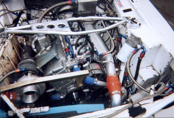
425 hp @ 15 lbs boost or 645 hp @ 25 lbs boost (claimed)
Building a 'bolt-on' system, which is the most common question I receive, first thing is to locate or build a turbo exhaust manifold. I recommend using the Garrett T3 exhaust housing as this will allow for the use of commonly available turbochargers. The other benefit of using the T3 exhaust housing is the expandability it allows, any combination of T3 as well as T04B & E compressor housings can be fitted. Allowing 200-450hp+ flow capacities which will be all you could ever need and more in a street application. Another advantage the T3 provides is access to compressor maps which will ease selection of the turbocharger to match your needs.
Compressor Housing Selection
How do you select a compressor? First thing is to understand what your looking at with the Map.
Pressure Ratio: (boost pressure + atmospheric pressure)/atmospheric pressure
(10 psi boost + 14.5 psi)/14.5 = 1.7
Air Flow(lbs/min): This is the air flow you calculate based on engine displacement, boost
level, volumetric efficiency(VE), RPM
How do I figure out the Air Flow of my engine? This is complex, basically to simplify this enough to select the best turbocharger comes down to calculating theoretical volumetric efficiency.
VE=(792001.6*(RWHP/0.83))/(RPM * Displacement in in3 * AP * CR)
Where:
VE = Volumetric Efficiency (Theoretical)
RWHP = Rear Wheel Horse Power
Displacement in in3= Engine displacement in cubic inches (2.0L = 122 in3)
AP = Atmospheric Pressure (~14.5 psi depending on altitude)
CFM=(122*RPM*VE%)/3456
CR = Compression Ratio (Static is close enough)
* The better the information plugged into the formula the more accurate the output.
Conversions: Lbs/min = 0.0756 x CFM
So with a dyno plot of an M10 engine

Steve
Kupper's
1970
BMW
2002
ITG
filter,
38/38
weber
carb.
peanut
intake,
292
cam,
9.5:1
pistons,
Tii
exhaust
manifold.
2
1/4"
pipe,
2
MagnaFlow
glass
packs.
We calculate these numbers which can then be used to determine CFM (Lbs/min) at rpm:
83%
VE
at
2500
rpm
=
73
CFM
=
5.5
lbs/min
x
1.7*
=
9
lbs/min
**
87%
VE
at
3000
rpm
=
92
CFM
=
7.0
lbs/min
x
1.7
=
12
lbs/min
98%
VE
at
3500
rpm
=
121
CFM
=
9.1
lbs/min
x
1.7
=
16
lbs/min
105%
VE
at
4000
rpm
=
148
CFM
=
11.1
lbs/min
x
1.7
=
19
lbs/min
105%
VE
at
4500
rpm
=
166
CFM
=
12.5
lbs/min
x
1.7
=
21
lbs/min
102%
VE
at
5000
rpm
=
180
CFM
=
13.6
lbs/min
x
1.7
=
23
lbs/min
99%
VE
at
5500
rpm
=
192
CFM
=
14.5
lbs/min
x
1.7
=
25
lbs/min
95%
VE
at
6000
rpm
=
201
CFM
=
15.2
lbs/min
x
1.7
=
26
lbs/min
85%
VE
at
6500
rpm
=
195
CFM
=
14.7
lbs/min
x
1.7
=
25
lbs/min
* 1.7 is the pressure ratio (10 psi boost)
** full boost at 2500 rpm is possible and should be used to make sure the surge line is not crossed at low RPM's.
Are these numbers exact? I would doubt it but for figuring out rough air flow numbers which we will use to select a turbocharger compressor they are close enough. Having access to better data will make this selection more accurate. Better to build the engine, turbocharge it and then dyno test to get these numbers much more accurately. The pressure ratio is at the turbochargers compressor so any losses into the manifold needs to be added. Typically 1-2+ psi can be lost depending on piping layout and the intercooler.
Again this is not science, but rather more of an educated guess. Since I used data from a normally aspirated engine with high compression and a camshaft the data is not ideal. The high rpm full boost area is starting to get off the efficiency map, down below 65%, but the mid range area is right in the peak efficiency zone.
The '60' trim T3 compressor would make a good choice for a street turbo ~10psi boost, but perhaps not the best choice for a road racing car.
Something to understand is boost pressure isn't the end all be all. It is quite possible to have more power with less boost pressure on otherwise identical engines. A turbo which is forced to work outside its peak efficiency range is not going to provide as much power. This is why turbocharger selection is so important. It's all about compromises.
Exhaust housing selection
Now this is much more complicated to calculate, experience is necessary to choose correctly. Some common choices available are A/R ratio, turbine wheel, extruder outlet size (goes together with turbine wheel selection). A good start for a 2.0L M10 street engine would be a 0.63 A/R housing and standard wheel. For a 1.8L M10 perhaps a 0.48 A/R housing and standard wheel. These are good starting points for low boost (~10psi) applications, more boost/and or RPM's means more exhaust flow which requires larger extruder outlets and turbine wheels.
Problems
-Sluggish boost rise at low RPM's may mean the A/R is too large, while quick response which causes surge problems can be an A/R that is too small.
-Power tapering off at higher RPM's can be a sign of the extruder outlet being too small which is causing high back-pressure between the engine and the turbine. Or an improperly sized compressor that is working too hard.
Exhaust System
What size exhaust pipe should be used? 2.5" ID pipe is plenty for street use, 2.75" ID at a maximum. Not much of a muffler is required as well, I would not recommend skipping the muffler for the street though.
Wastegates
The wastegates job is to control the exhaust flow into the turbochargers turbine to maintain a set boost pressure. It basically allows part of the exhaust to bypasses the turbocharger.
There are two basic types, internal and external (from the turbocharger), the internal is what is commonly on production turbocharged engines. It shares its outlet with the turbine which makes it less then ideal for flow. External wastegates in my opinion are the only way to go, with the dump located to atmosphere in a separate pipe. Optionally the dump can be routed back into the exhaust at least 2 feet away from the turbine outlet. Dumping straight to atmosphere is equivalent to running one of the primary pipe as an open header, very loud. But only under full throttle full boost.
What next?
Oil supply and return to the turbocharger, turbochargers need lubrication to their center bearings to survive the 100,000+rpm's that they can be subjected too. A good place to get the oil from is near the oil pressure switch on the distributor housing. The housing is thick enough to drill and tap for a fitting. Make sure to use a flexible steel braided line rated for at least 250 Degrees F and 100 psi+ pressure. Oil returned from the turbocharger need to get back inside the engine, this can be tricky and is another factor in turbocharger placement. I used the side of the block, drilled and tapped for a fitting. The return line should be much larger inner diameter tubing (3/8"-1/2" ID). Extra care should be taken to insure there are no oil leaks.
Intercooling
Do I need an intercooler? Well that depends, if you have correctly sized the turbocharger for your application and only plan on running a maximum of ~10psi boost then you can probably do without the intercooler. It will make more power with a proper intercooler.
What does it do? An intercooler is basically a heat exchanger similar to your radiator. As the turbocharger compresses the air it gets heated (not because of the exhaust temperature as some people seem to think). The amount it gets heated depends on the efficiency of the turbo. The formula for calculating the discharge temperature is:
Tout = Tin + (Tin x [-1+(Pout/Pin)0.263]) / eff
Tin = Inlet temperature (ambient) in deg R (example 80 deg F + 460 = 540 deg R)
Pout = pressure out of the compressor in absolute (boost pressure + atmospheric pressure)
Pin = use a slight vacuum -0.5 psi + atmospheric pressure.
Tout will be in deg R so subtract 460 from this to find deg F.
Since cooler air is more dense it makes sense to want to lower its temperature, as the hot compressed air passes through the intercooler it transfers it energy to the aluminum in the intercooler core which can then be transfered to the ambient outside air flowing through the core. The intercooler acts like a big heat sink. Now this can have a negative effect of heating the inlet air after some hard use.
What about water/air intercoolers, where water is used to remove the heat from the core. This is a good idea for drag racing, and perhaps it would be good for street use. Road racing is not a good application.